TCD italia
Flare supporting structures
There are several types of support methods for elevated flares.
TCD Italia optimizes the structural impact by careful consideration of all relevant factors as a first step to an economic final solution.
TCD Italia has the experience to propose any type of flare supporting structure and it is in a position to provide the structural and mechanical design, fabrication, trial assembly and erection.
Design is in accordance with all worldwide current used codes employing advanced finite elements and dynamic simulation techniques.
The types of structures are:
– Self-supported
– Guyed
– Derrick
– Guyed constant derrick
– Demountable derrick-supported flare
A thorough evaluation of the specific needs will ensure that economic and operational considerations are fully taken into account before one comes to a decision.
Self-supported flare
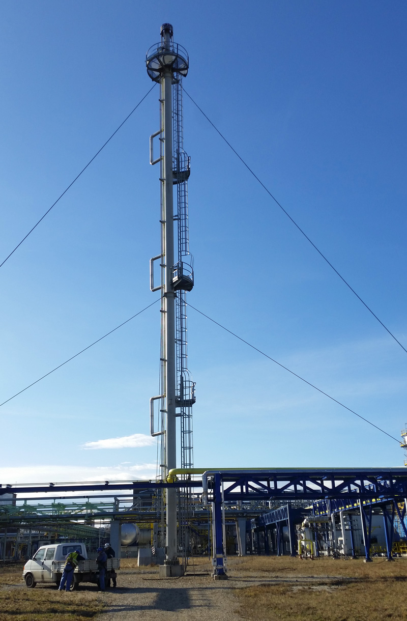
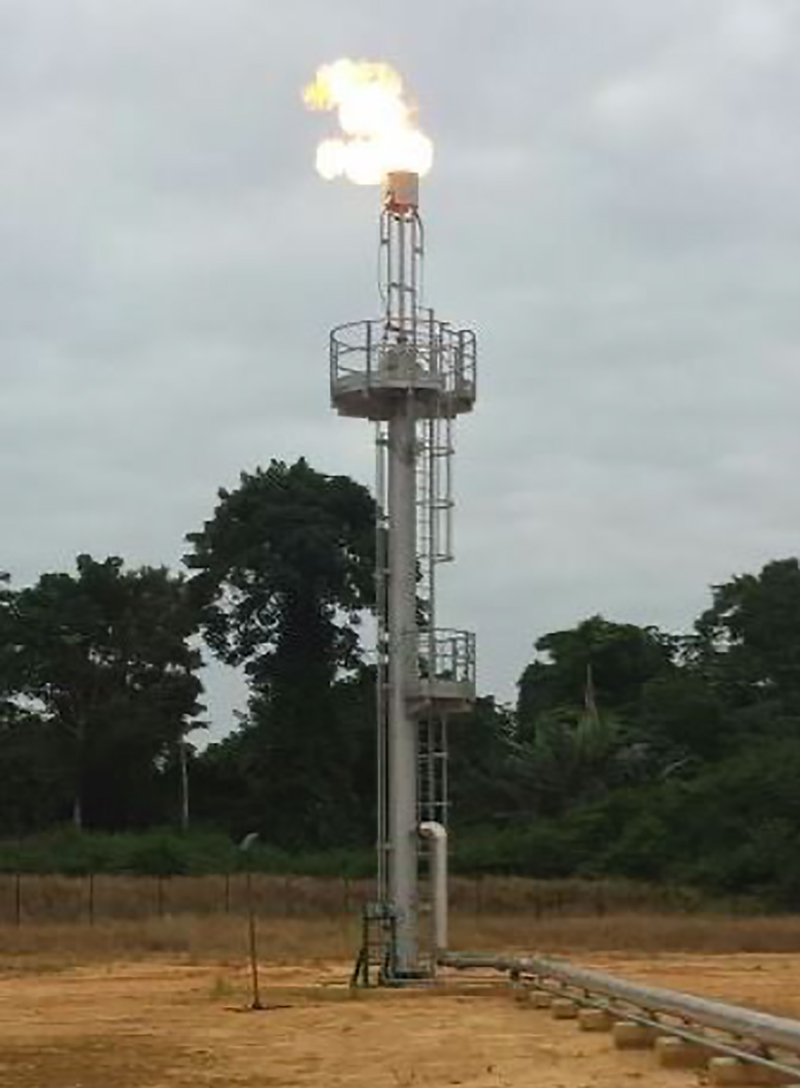
A mechanically and structurally designed stack supports the flare tip without any extra support.
With high flaring rates it is possible to achieve very cost effective designs because riser diameters approach the larger dimensions required for structural stability.
This type of support is usually required when space is not available for other type of supporting structure.
Usually the top flare elevation with type of structure is limited to 70 m high.
TCD Italia can offer “variable section diameter” support stacks.
The lower portion of the self-supported flare can be occasionally adapted as an integral Liquid Seal and/or Knock-Out Drum.
For short flares a self-supported flare will probably involve the smallest capital cost and be fairly easy to erect and maintain.
Guyded-supported flare
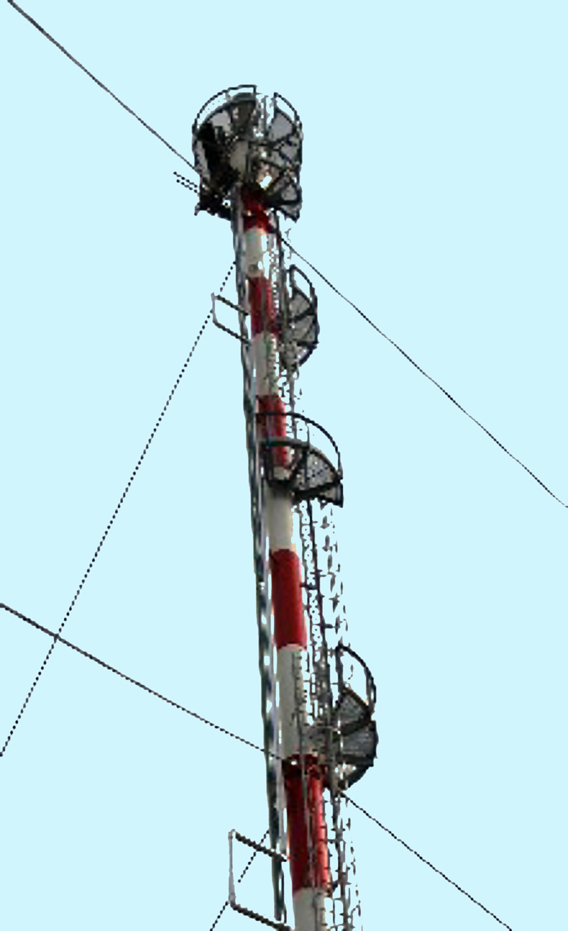
This type of support represents the lightest and cheapest option.
It can be used when space and plant layout are large enough to accommodate the guy ropes anchor points at grade.
Three deadmen usually anchor up to fire ropes from the flare stack.
Flare riser diameters are usually governed by the flaring gas process requirements.
However, careful consideration of vibration behavior is necessary as well as flaring gas temperature that can produce significant expansion of the stack.
Usually flaring gas over 250°C prevents the use of guyed structures.
It is realistic also to say that over 150 m flare elevation the guyed flare structure is not a practical design.
To reduce maintenance problems wire rope cores should be used rather than fibre cores and ropes and fittings are hot dip galvanized.
Guyded constant derrick-supported flare
This type of support is a good technical and cost compromise when high value of gas temperature could produce significant expansion of the riser and the setting of guy ropes supporting system will represent a problem.
Under these circumstances a constant derrick structure (triangle or square shape) is a widely used method.
The flare riser(s) is / are located within the constant derrick so that it is free to move and to expand as well as ladders and platforms and service piping.
The constant derrick (not the flare riser) would be supported by guy-ropes at different elevation.
The main columns of the constant derrick are in tubular carbon steel pipes, cross member can be in tubular or open profile,
The constant derrick modules will not exceed 12 m flanged length and all elements are bolted individually.
A full hot dip galvanization will ensure complete corrosion protection.
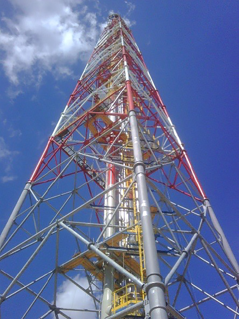
Derrick-supported flare
The derrick-supported structure is used for very tall systems where the use of a guy wire is not allowed due to space and erection problems.
The flare riser is housed within and supported by a braced framework.
The flare burner can be maintained by lowering it by a davit or a crane.
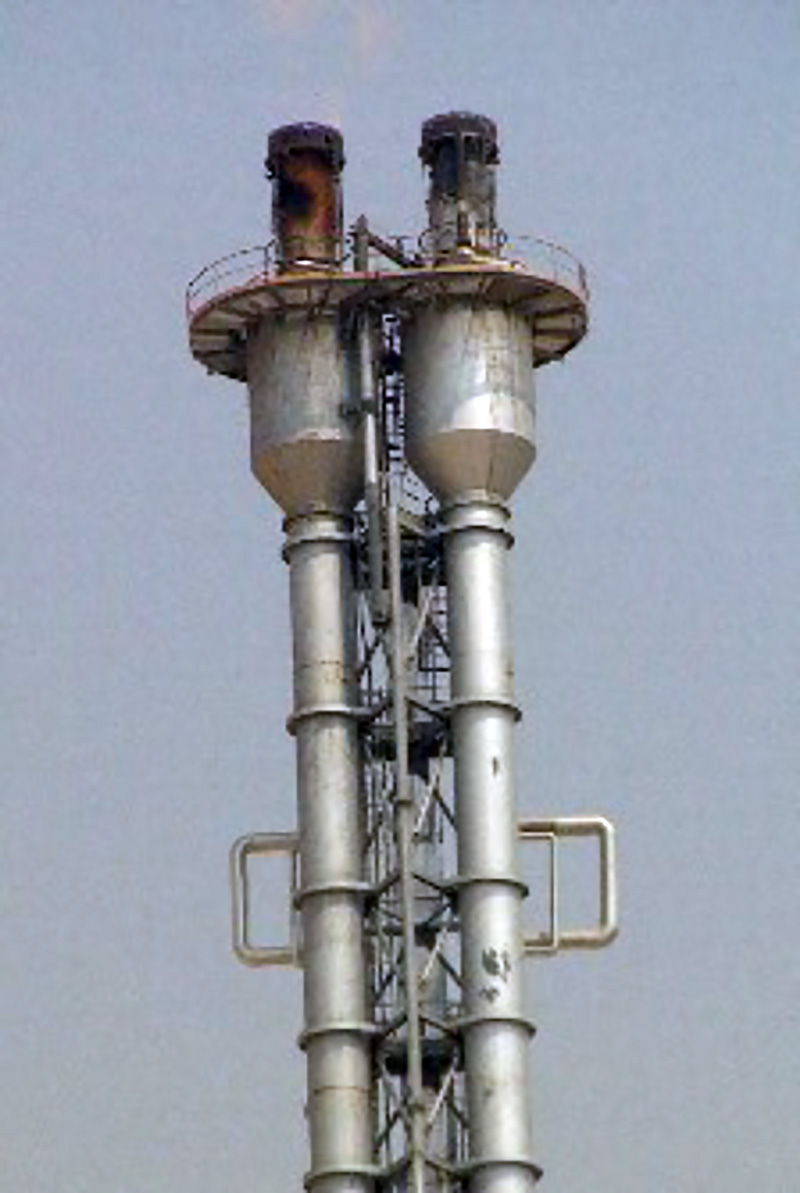
The derrick structure allows the installation of several flares together.
Derricks can have square or triangle shape and they can be fabricated from tubular carbon steel or open profile or a mix of them.
All members (main columns, cross bracing) are usually of all bolted construction and supplied in 12 m max. length.
All derrick and riser components will be hard stamped by individual mark and easily identified by the erection drawings.
The derrick will be trial-assembled at workshop’s and usually hot dip galvanized in order to ensure complete corrosion protection.
The derrick is so designed that erection can be accomplished in approximately 12 m sections. The structure is flexible in style to suit erection needs and it may be erected piecemeal where only limited craneage is available.
Demountable derrick-supported flares
The TCD Italia derrick-supported flares offer several advantages if it is required to carry on maintenance to a flare.
Many demountable derrick-supported flares are designed to support multiple risers with their flare burners.
Such a type of flare system is designed so that all the flares, except the ones being maintained, can be in operation during the maintenance.
In this system the flare riser(s) and the relevant service piping are supplied in flanged sections (approx. 25 m long). This arrangement allows each flare riser to be lowered at grade for flare burner maintenance.
Each flare riser section is provided with supporting arms, adequate sliding points (rollers) suitable to operate in the guide rails which will be fixed to the derrick structure.
To perform raising and lowering of each flare stacks, stairs ladders, platforms, winches, pulleys, blocks, steel wires, support tools are supplied with the system.
Winches are provided with an automatically operated brake to prevent an accidental releasing of the load.
Each flare stack is supported at the bottom on a hinged canting plate which allows the flanged sections to cant during stack change out.
The derrick structure is usually fabricated from tubular pipe (open lattice type). The design considers all the stresses induced by the flare risers due to lighting operation.
The derrick structure includes guide rails and a thermal radiation shield usually installed above the working platform used during canting/lighting operations as protection for personnel.
Advantages over conventional derrick-fixed flares
– Several flares can be easily fitted in a single structure
– Flare burners maintenance can be done from grade while the other flares are in operation
– The derrick can be designed to accommodate future flares which can be erected without the need of plant shut-down and inducing cranes costing.
The derrick structure has a bolted design supplied in flanged length suitable for transportations.
The bolted construction of each element of the derrick eliminates any site welding during erection.
The derrick will be trial-assembled at workshop’s and hot dip galvanized in order to ensure complete corrosion protection.
Usually two types of demountable derrick flares are in use today:
a) – Square derrick supporting an inner box where the demountable flare risers are installed (in practice the flare risers are inside the derrick and they are entirely free floating retained by spring loaded rollers acting on guide tube)
b) – Three side or rectangular shape derrick where the demountable flare risers are located on a single flat side of a derrick structure and located onto the structure by sliding rails system.
TCD Italia is in a position to design and fabricate both above mentioned structure.
The selection of solution a) or b) is mainly due to flare elevation and riser diameters.
The problem in selecting solution a) is that as riser sizes and heights increase the offset lifting forces require to raise and lower the risers.
These forces are a result of the impossibility of obtaining a straight vertical lift of the risers. The result is that the offset forces increase the frictional loads acting through the guide rails.
In the solution b) the risers are fully floating and loosely guided only by spring loaded rollers. As a result frictional loads are minimal and a straight fully balanced lift is obtained.
Flare riser erection and dismounting procedure
The erection procedure should take place under suitable meteorological conditions with a wind speed not greater than 50% of the design wind speed.
Canting and hoisting pulley blocks, cables should be placed into position using a swell service crane. Winches should be verified for a proper operation.
The upper section of the flare riser, including flare burner, should be horizontally placed and bolted to the hinged canting base plate. Then put in a vertical position using the canting winch, fix the hoisting pulley block and unbolt the riser section from the hinged canting base plate. The upper section of the flare is ready to be lifted by the hoisting winches to a sufficient elevation to allow the second riser section to be installed below it.
The second riser section is installed by canting it into position beneath the first section.
The two sections are then bolted together as well as all the attached service piping. They are then lifted as one piece in a way that the further riser section can be positioned underneath.
The above operations are repeated until the flare burner is in the final operating position and the lower flare riser section is in a place to be connected to the flare header.
To dismount the flare risers use the reverse sequence.

HEAD OFFICE:
Via Bachelet, 81/83
46047 Porto Mantovano
Mantova – Italy (MN)
WORKSHOP:
Via Pitentino, 5
46037 Governolo di Roncoferraro
Mantova – Italy (MN)
Phone: +39 0376 408149
Email: info@tcd-italia.com
P. IVA: 02453260206


